I am going to go ahead and get this tutorial started, though it will likely be a work in progress.
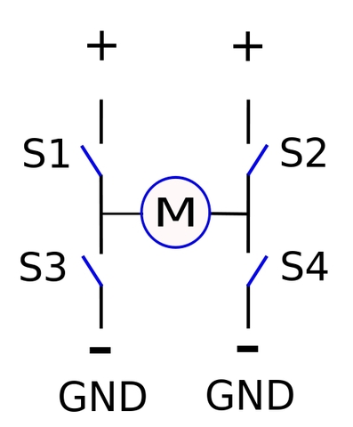
The H-bridge is an interesting concept that is the digital equivalent to a set of train tracks switching to make a train go a different direction when needed. The H-bridge is a set of 4 switches (simple switches), aligned so that when turned on in opposite pairs they will produce different results, like changing the direction of a DC motor. You can go quite deep into this theory, as there are many factors that will affect how the H-bridge operates, but we will start small and simple and work up so you can drop out at any time and start playing.
Before getting started with the H-bridge, let's assume we need to control a standard DC motor that has 2 control wires. The control wires of a DC motor can have voltage applied in any direction without hurting the motor. Applying positive to one side and negative to the other will cause the motor to spin in one direction, swapping the polarity of the wires will cause it to spin in the other direction. Applying either positive or negative to both wires at the same time will cause a condition called "electric braking" in which the motor resists spinning at the output shaft - this is acceptable to do and sometimes desired in certain situations. Take a look at the most basic way to power a DC motor:

Now to keep from having to permanently connect the wires from each motor to the battery (removing the ability to reverse directions), we can install a set of switches at each motor terminal wire and route the desired polarities to the motor terminals using the switches. The size and type of switch used is unimportant when trying to understand how an H-bridge works, so we will leave those details out for now - knowing that it switches power to each Motor terminal is what is important.
In the main image, the top leads from Switches 1 and 2 are shown separately connected to the + power supply to depict the shape of the "H". In reality, these leads are usually connected together to the positive battery terminal (likewise for the GND terminals). Please take a look at the image below of the different possible H-bridge "states" - these are different ways you could control an H-bridge correctly and the result of each. The circled M in each picture represents a standard DC motor and its 2 wires, the orange circling arrows depict the motor shaft rotational direction, and the green arrows depict the flow of current through the motor (load).

As a reminder, when a switch is "open", that means its terminals are disconnected from each other - when the switch is "closed", its terminals are being connected together. As you can see, each of the above control methods is OK and will not harm the H-bridge. You might notice that with each of the above scenarios, never are both switches on the same side (Left = S1 and S3) or (Right = S2 and S4) closed at the same time - this is because doing so would cause a short circuit (also called "Shoot Through"), allowing the electrical current to flow directly from the positive supply to the negative supply with no resistance. Causing a short circuit will burn the weakest point of the circuit, usually the wire or switches, so this is never a good idea (see below):

On that note, don't blow up your H-bridges, and I will post more soon....